This is the fourth part of my VCAP7-DTM Design exam series. In part 3 I covered the creation of a logical design for Horizon 7. This time we take a look at section 3 of the blueprint, the creation of a physical design:
Section 3 – Create a Physical Design for vSphere and Horizon Components
Objective 3.1 – Create a Horizon Pod and Block Architecture Design
Objective 3.2 – Extend Horizon Architecture Design to Support Additional Horizon Suite Components
Objective 3.3 – Design vSphere Infrastructure to Support a Horizon Implementation
Objective 3.4 – Add Required Services to Support a Given vSphere Design
Physical diagrams contain more details than the logical architecture and could can brand names or models of storage arrays, network switches and so on. In the physical design we will describe individual parameters or settings for each component.
VMware Horizon Block and Pod Design
A VMware Horizon solution includes one or more Horizon instances, where a Horizon instance is a pod that includes one or more building blocks.
A building block consists of physical servers, a vSphere infrastructure, Horizon 7 servers, shared storage, and virtual machine desktops for end users. A building block is a logical construct and should not be sized for more than 2’000 Horizon desktops. Customers usually include up to five building blocks in a Horizon 7 pod, although in theory you can use more blocks than that, as long as the pod does not go above 10’000 sessions and 7 Horizon Connection Server instances.
The Cloud Pod Architecture (CPA) feature allows you to link multiple Horizon pods together (using the View Inter-Pod API (VAPI) protocol) to provide cross-data center administration and to perform local or global user-to-desktop mappings (entitlements). In a traditional Horizon implementation you manage each pod independently.
There are two different kind of building blocks, the management block (only one) and the resource block (up to 5 in a Horizon pod)
VMware recommends about 2’000 sessions or desktops in a Horizon resource block which includes at least one Horizon Connection Server (CS). In addition to the CS other components like ESXi hosts, vSphere clusters, desktop and application pools and storage form a VMware Horizon resource block.
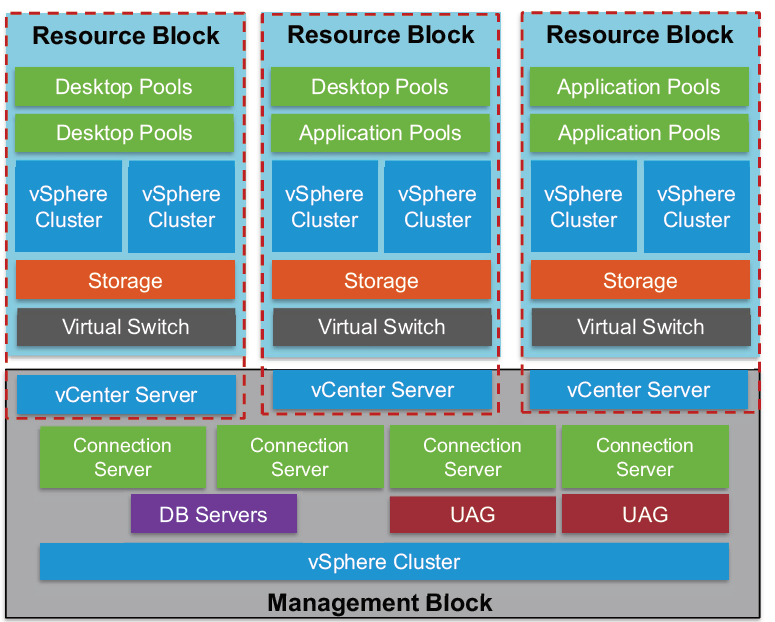
One Horizon pod can contain up to 10’000 sessions or desktops and 7 Connection Server instances. For environments exceeding the 10’000 users, you have to leverage the Cloud Pod Architecture feature with the usage of load balancers.
In the image above each Horizon 7 resource block has its own vCenter Server. Since View 5.2 and later customers have the ability to use a single vCenter Server instance to manage a 10’000 desktop environment. Although using one vCenter Server for 10’000 desktops is possible and supported, doing so is not recommended because this design creates a single point of failure. The loss of that single vCenter Server prevents any desktop power management, provisioning and other operations.
The Horizon 7 management block consists of the VMs that are supporting the block and pod infrastructure:
vCenter Server instances, Horizon infrastructure servers, Connection Servers, database servers, Composer, UAG, Active Directory, DNS, DHCP, Certification Authorities etc.
Horizon Component Design
To be able to deliver the Horizon 7 services, we first need to design and build the required infrastructure components.
VMware Identity Manager (vIDM) provides the optional WorkspaceONE portal which provides access to different types of applications (Horizon desktop & apps, SaaS-based web apps, ThinApp packaged applications and even Citrix-based application an desktops). Even vIDM is available from on-premises installation, VMware recommends a SaaS-based implementation.
Following VMware’s recommendations, you will need at least three vCenter Server instances:
– 1 vCenter Server for every 2’000 desktops
– 1 vCenter Server for the Horizon management block
– 1 vCenter Server for the vCenter Server Management cluster
(with all vCenter Servers including networking and security instances)
Each Horizon Connection Server provisioned with the minimum supported system specifications should be able to manage the connectivity for up to 2’000 users. If you are using Blast Secure Gateway connections to desktops using HTML access, the Connection Server only can have a maximum of 800 connections. A minimum of two Connection Servers is recommended for failover and redundancy reasons.
VMware supports a maximum of seven active Connection Servers per replication group because of Java Message Services (JMS) performance limitations.
Connection servers are active only if they are enabled in Horizon Administrator to accept
connections. A disabled connection server communicates with other connection servers in the group
and replicates the LDAP directory.
This means that, if you have deployed the maximum of 7 Connection Servers, five have to be enabled and two disabled.
Although View Composer can be installed on the same server as the Windows vCenter Server, for larger environments VMware recommends that you install View Composer on a standalone server. Each Composer server requires a unique Composer database. However, multiple Composer databases can be placed on a single SQL instance. A View Composer server is always paired with a vCenter Server for each Horizon block. If possible, VMware recommends using the Instant Clone technology which doesn’t need additional infrastructure servers.
The Unified Access Gateway (UAG) is the new way to allow remote connections and has the same features like the old View Security Server. The UAG appliance (VM based on Linux) is normally installed in the DMZ and enables secure access from outside the corporate network to the internally hosted desktop and application servers. Unlike a Security Server, the UAG appliance doesn’t need to be paired with a specific Connection Server. VMware recommends the usage of a UAG than Security Server.

This is it. 🙂 The next article focuses on section 4 where the design for Horizon storage is the topic.
