OCI Network Firewall Powered by Palo Alto Networks

OCI Network Firewall Powered by Palo Alto Networks

Enterprises running workloads in Oracle Cloud Infrastructure (OCI) often look for deeper inspection, granular control, and consistent policy enforcement. Capabilities that extend beyond the functionalities of basic security groups and route tables.

Historically, many teams implemented these capabilities by deploying virtual appliances or building complex service chains using native components. While functional, those approaches introduced operational complexity, created scaling challenges, and often led to inconsistent enforcement across environments.

To address this, in May 2022, Oracle introduced the OCI Network Firewall, a fully managed, stateful, Layer 7-aware firewalling service built into the OCI platform powered by Palo Alto Networks’ virtual firewall technology. Unlike virtual appliance deployments, this service is provisioned and managed like any other OCI resource, offering deep packet inspection and policy enforcement without requiring the management of underlying infrastructure.

How the OCI Network Firewall Works

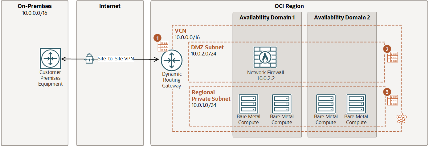
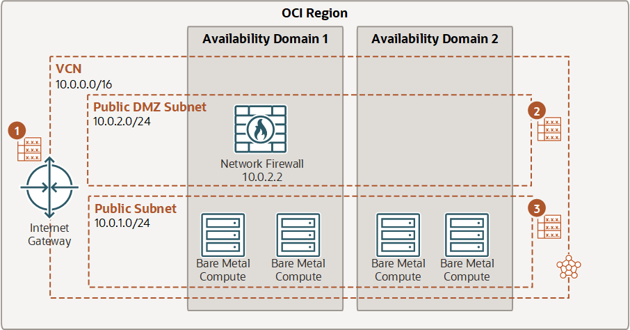
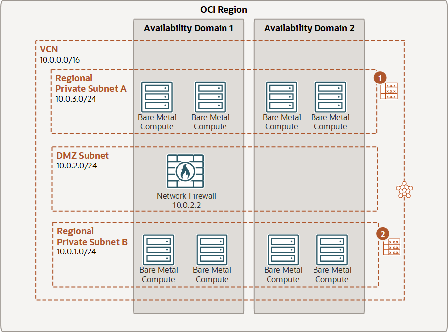
The OCI Network Firewall is deployed as a centralized, stateful firewall instance inside a Virtual Cloud Network (VCN). It operates as an inline traffic inspection point that you can insert into the flow of traffic between subnets, between VCNs, or between a VCN and the public internet. Instead of managing a virtual machine with a firewall image, you provision the firewall through the OCI console or Terraform, like any other managed service.

Under the hood, the firewall is powered by the Palo Alto Networks VM-Series engine. This enables deep packet inspection and supports policies based on application identity, user context, and known threat signatures – not just on IP addresses and ports. Once provisioned, the firewall is inserted into traffic paths using routing rules. You define which traffic flows should be inspected by updating route tables, either in subnets or at the Dynamic Routing Gateway (DRG) level. OCI automatically forwards the specified traffic to the firewall, inspects it based on your defined policies, and then forwards it to its destination.

OCI Network Firewall use case diagram, description below

Logging and telemetry from the firewall are natively integrated with OCI Logging and Monitoring services, making it possible to ingest logs, trigger alerts, or forward data to external tools. Throughput can scale up to 4 Gbps per firewall instance, and high availability is built into the service, with deployments spanning fault domains to ensure resiliency.

OCI Network Firewall is a highly available and scalable instance that you create in a subnet. The firewall applies business logic specified in a firewall policy attached to the network traffic. Routing in the VCN is used to direct traffic to and from the firewall. OCI Network Firewall provides a throughput of 4 Gb/sec, but you can request an increase up to 25 Gb/sec. The first 10 TB of data is processed at no additional charge.

The firewall supports advanced features such as intrusion detection and prevention (IDS/IPS), URL and DNS filtering, and decryption of TLS traffic. Threat signature updates are managed automatically by the service, and policy configuration can be handled via the OCI console, APIs, or integrated with Panorama for centralized policy management across multi-cloud or hybrid environments.

Integration with Existing OCI Networking

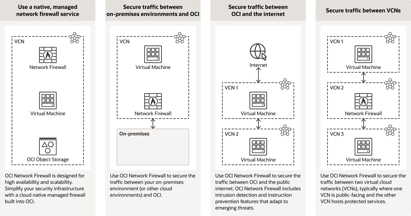
OCI Network Firewall fits well into the kinds of network topologies most commonly used in OCI, particularly hub-and-spoke architectures or centralized inspection designs. In many deployments, customers set up multiple workload VCNs (the spokes) that connect to a central hub VCN via local peering. The hub typically hosts shared services such as logging, DNS, internet access via a NAT gateway, and now, the network firewall.

By configuring route tables in the spoke VCNs to forward traffic to the firewall endpoint in the hub, organizations can centralize inspection and policy enforcement across multiple VCNs. This model avoids having to deploy and manage firewalls in each spoke and enables consistent rules for outbound internet traffic, inter-VCN communication, or traffic destined for on-premises networks over the DRG.

OCI Network Firewall Hub and Spoke

Source: https://docs.oracle.com/en-us/iaas/Content/Resources/Assets/whitepapers/learn-oci-network-firewall-with-examples.pdf 

The insertion of the firewall is purely routing-based, meaning there’s no need for IPsec tunnels or overlays to redirect traffic. As a result, latency is minimal and the setup remains relatively simple. With high availability built in and native integration into OCI’s monitoring and logging stack, the firewall becomes a part of the existing infrastructure.

Design Considerations

While the OCI Network Firewall removes much of the operational burden of managing security appliances, there are still architectural choices that influence how effective the deployment is. One key consideration is routing. Since traffic inspection is based on routing decisions, the firewall only sees traffic that has been explicitly directed through it. That means route tables must be carefully designed to forward the correct flows.

Firewall placement also plays a role in the overall design. Centralized deployment in a hub VCN can simplify management and enforce consistent policy, but it might introduce additional hops in the network path. Depending on the traffic patterns and latency sensitivity of your applications, you may need to evaluate whether east-west inspection should also be enabled or limited to specific flows.

Monitoring and visibility should be planned from the start. Logging is not retained indefinitely, so integrating logs with OCI Logging Analytics, pushing them to a SIEM, or exporting them to object storage for long-term retention is a best practice. You should also account for log volume and potential cost, especially in high-throughput environments.

Throughput limits are another factor. As mentioned before, a single firewall instance supports up to 4 Gbps, so if your architecture requires higher performance, you may need to segment inspection points or scale up to 25 Gbps upon request. Understanding these thresholds is important when designing for resilience and future growth.

Finally, while the firewall is managed, policy complexity still needs governance. Deep inspection features can be powerful but require thoughtful rule design to avoid unnecessary latency or policy overlap.

Final Thoughts

The OCI Network Firewall adds a much-needed layer of native, centralized security enforcement to Oracle Cloud. It brings next-generation firewall capabilities into the platform in a way that aligns with how modern infrastructure is built: with automation, centralized control, and reduced operational overhead. For teams that have struggled to scale or standardize firewalling in OCI using virtual appliances, this service simplifies a lot of that work.

That said, it’s still a tool. Its effectiveness depends on how well it’s integrated into your network design and how clearly your security policies are defined. For organizations moving toward more distributed architectures or running regulated workloads in OCI, it’s a step in the right direction – a platform-native way to improve visibility and control without losing flexibility.

Note: Please be aware that OCI Network Firewall design concepts and configurations are part of the Oracle Cloud Infrastructure 2025 Networking Professional exam.

From Castles to Credentials – Why Identities Are the New Perimeter

From Castles to Credentials – Why Identities Are the New Perimeter

The security world has outgrown its castle. For decades, enterprise networks operated on the principle of implicit trust: if a device or user could connect from inside the perimeter, they were granted access. Firewalls and VPNs acted as moats and drawbridges, controlling what entered the fortress. But the rise of clouds, remote work, and APIs has broken down those walls by replacing physical boundaries with something far more fluid: identity.

This shift has led to the emergence of Zero Trust Architecture (ZTA), which flips the traditional model. Instead of trusting users based on their location or device, we now assume that no actor should be trusted by default, whether inside or outside the network. Every access request must be verified, every time, using contextual signals like identity, posture, behavior, and intent.

But “Zero Trust” isn’t just about a philosophical change but about practical design as well. Many organizations start their Zero Trust journey by microsegmenting networks or rolling out identity-aware proxies. That’s a step in the right direction, but a true transformation goes deeper. It redefines identity as the central pillar of security architecture. Not just a gatekeeper, but the control plane through which access decisions are made, enforced, and monitored.

The Inherent Weakness of Place-Based Trust

The traditional security model depends on a dangerous assumption: if you are inside the network, you are trustworthy. That might have worked when workforces were centralized and systems were isolated. With hybrid work, multi-cloud adoption, and third-party integrations, physical locations mean very little nowadays.

Attackers know this. Once a single user account is compromised via phishing, credential stuffing, or social engineering, it can be used to move laterally across the environment, exploiting flat networks and overprovisioned access. The rise of ransomware, supply chain attacks, and insider threats all originate from this misplaced trust in location.

This is where identity-based security becomes essential. Instead of relying on IP addresses or subnet ranges, access policies are tied to who or what is making the request and under what conditions. For example, a user might only get access if their device is healthy, they are connecting from a trusted region, and they pass MFA.

By decoupling access decisions from the network and basing them on identity context, organizations can stop granting more access than necessary and prevent compromised actors from gaining a foothold.

Identities Take Center Stage

Identities are multiplying rapidly, not just users, but also workloads, devices, APIs, and service accounts. This explosion of non-human identities creates a massive attack surface. Yet, in many organizations, these identities are poorly managed, barely monitored, and rarely governed.

Identity-Centric Zero Trust changes that. It places identity at the center of every access flow, ensuring that each identity, human or machine, is:

  • Properly authenticated

  • Authorized for just what it needs

  • Continuously monitored for unusual behavior

Example: A CI/CD pipeline deploys an app into production. With traditional models, that pipeline might have persistent credentials with broad permissions. In an identity-centric model, the deployment service authenticates via workload identity, receives just-in-time credentials, and is granted only the permissions needed for that task.

This model reduces privilege sprawl, limits the blast radius of compromised credentials, and provides clear visibility and accountability. It’s about embedding least privilege, lifecycle management, and continuous validation into the DNA of how access is handled.

Routing With Intent

Zero Trust doesn’t mean the network no longer matters, it means the network must evolve. Today’s networks need to understand and enforce identity, just like the access layer.

A good example of this is Oracle Cloud Infrastructure’s Zero Trust Packet Routing (ZPR). With ZPR, packets are only routed if the source and destination identities are explicitly authorized to communicate. It’s not just about firewall rules or ACLs but also about intent-based networking, where identity and policy guide the flow of traffic. A backend service won’t even see packets from an unauthorized frontend. Routing decisions happen only after both parties are authenticated and authorized.

This is part of a bigger trend. Across the industry, cloud providers and SDN platforms are starting to embed identity metadata into network-level decisions, and routing and access enforcement are being infused with contextual awareness and identity-driven policies.

For architects and security teams, this opens new possibilities for building secure-by-design cloud networks, where you can enforce who talks to what, when, and under what conditions, down to the packet level.

Identity as the Control Plane of Modern Security

If Zero Trust has taught us anything, it’s that identity is the new perimeter and that it’s the control plane for the entire security architecture.

When identity becomes the central decision point, everything changes:

  • Network segmentation is enforced via identity-aware rules

  • Application access is governed by contextual IAM policies

  • Monitoring and detection pivot around behavioral baselines tied to identity

  • Automation and response are triggered by anomalies in identity behavior

This model allows for granular, adaptive, and scalable control, without relying on fixed infrastructure or fragile perimeters. It also provides a better experience for users: access becomes more seamless when trust is built dynamically based on real-time signals, rather than static rules.

Image with no description

Importantly, this approach doesn’t require a big bang overhaul. Organizations can start small by maturing IAM hygiene, implementing least privilege, or onboarding apps into SSO and MFA, and build toward more advanced use cases like workload identity, CIEM (Cloud Infrastructure Entitlement Management), and ITDR (Identity Threat Detection and Response).

Concluding Thoughts

We need a security model that reflects that reality. Perimeters no longer define trust. Location is no longer a proxy for legitimacy. And static controls are no match for dynamic threats – it’s like using static IPs when working with Kubernetes and containers.

Identity-Centric Zero Trust offers a modern foundation and a strategy. One that weaves together people, processes, and technologies to ensure that every access decision is intentional, contextual, and revocable.

Whether you are modernizing a legacy environment or building greenfield in the cloud, start by asking the right question.

Not “where is this request coming from?” but “who is making the request, and should they be allowed?”.

Can a Unified Multi-Cloud Inventory Transform Cloud Management?

Can a Unified Multi-Cloud Inventory Transform Cloud Management?

When we spread our workloads across clouds like Oracle Cloud, AWS, Azure, Google Cloud, maybe even IBM, or smaller niche players, we knowingly accept complexity. Each cloud speaks its own language, offers its own services, and maintains its own console. What if there were a central place where we could see everything: every resource, every relationship, across every cloud? A place that lets us truly understand how our distributed architecture lives and breathes?

I find myself wondering if we could one day explore a tool or approach that functions as a multi-cloud inventory, keeping track of every VM, container, database, and permission – regardless of the platform. Not because it’s a must-have today, but because the idea sparks curiosity: what would it mean for cloud governance, cost transparency, and risk reduction if we had this true single pane of glass?

Who feels triggered now because I said “single pane of glass”? 😀 Let’s move on!

Could a Multi-Cloud Command Center Change How We Visualize Our Environment?

Let’s imagine it: a clean interface, showing not just lists of resources, but the relationships between them. Network flows across cloud boundaries. Shared secrets between apps on “cloud A” and databases on “cloud B”. Authentication tokens moving between clouds.

What excites me here isn’t the dashboard itself, but the possibility of visualizing the hidden links across clouds. Instead of troubleshooting blindly, or juggling a dozen consoles, we could zoom out for a bird’s-eye view. Seeing in one place how data and services crisscross providers.

Multi-Cloud Insights

I don’t know if we’ll get there anytime soon (or if such a solution already exists) but exploring the idea of a unified multi-cloud visualization tool feels like an adventure worth considering.

Multi-Cloud Search and Insights

When something breaks, when we are chasing a misconfiguration, or when we want to understand where we might be exposed, it often starts with a question: Where is this resource? Where is that permission open?

What if we could type that question once and get instant answers across clouds? A global search bar that could return every unencrypted public bucket or every server with a certain tag, no matter which provider it’s on.

Multi-Cloud Graph Query

Wouldn’t it be interesting if that search also showed contextual information: connected resources, compliance violations, or cost impact? It’s a thought I keep returning to because the journey toward proactive multi-cloud operations might start with simple, unified answers.

Could a True Multi-Cloud App Require This Kind of Unified Lens?

Some teams are already building apps that stretch across clouds: an API front-end in one provider, authentication in another, ML workloads on specialized platforms, and data lakes somewhere else entirely. These aren’t cloud-agnostic apps, they are “cloud-diverse” apps. Purpose-built to exploit best-of-breed services from different providers.

That makes me wonder: if an app inherently depends on multiple clouds, doesn’t it deserve a control plane that’s just as distributed? Something that understands the unique role each cloud plays, and how they interact, in one coherent operational picture?

I don’t have a clear answer, but I can’t help thinking about how multi-cloud-native apps might need true multi-cloud-native management.

VMware Aria Hub and Graph – Was It a Glimpse of the Future?

Not so long ago, VMware introduced Aria Hub and Aria Graph with an ambitious promise: a single place to collect and normalize resource data from all major clouds, connect it into a unified graph, and give operators a true multi-cloud inventory and control plane. It was one of the first serious attempts to address the challenge of understanding relationships between cloud resources spread across different providers.

VMware Aria Hub Dashboard

The idea resonated with anyone who has struggled to map sprawling cloud estates or enforce consistent governance policies in a multi-cloud world. A central graph of every resource, dependency, and configuration sounded like a game-changer. Not only for visualization, but also for powerful queries, security insights, and cost management.

But when Broadcom acquired VMware, they shifted focus away from VMware’s SaaS portfolio. Many SaaS-based offerings were sunset or sidelined, including Aria Hub and Aria Graph, effectively burying the vision of a unified multi-cloud inventory platform along with them.

I still wonder: did VMware Aria Hub and Graph show us a glimpse of what multi-cloud operations could look like if we dared to standardize resource relationships across clouds? Or did it simply arrive before its time, in an industry not yet ready to embrace such a radical approach?

Either way, it makes me even more curious about whether we might one day revisit this idea and how much value a unified resource graph could unlock in a world where multi-cloud complexity continues to grow.

Final Thoughts

I don’t think there’s a definitive answer yet to whether we need a unified multi-cloud inventory or command center today. Some organizations already have mature processes and tooling that work well enough, even if they are built on scripts, spreadsheets, or point solutions glued together. But as multi-cloud strategies evolve, and as more teams start building apps that intentionally spread across multiple providers, I find myself increasingly curious about whether we will see renewed demand for a shared data model of our entire cloud footprint.

Because with each new cloud we adopt, complexity grows exponentially. Our assets scatter, our identities and permissions multiply, and our ability to keep track of everything by memory or siloed dashboards fades. Even something simple, like understanding “what resources talk to this database?” becomes a detective story across clouds.

A solution that offers unified visibility, context, and even policy controls feels almost inevitable if multi-cloud architectures continue to accelerate. And yet, I’m also aware of how hard this problem is to solve. Each cloud provider evolves quickly, their APIs change, and mapping their semantics into a single, consistent model is an enormous challenge.

That’s why, for now, I see this more as a hypothesis. An idea to keep exploring rather than a clear requirement. I’m fascinated by the thought of what a central multi-cloud “graph” could unlock: faster investigations, smarter automation, tighter security, and perhaps a simpler way to make sense of our expanding environments.

Whether we build it ourselves, wait for a vendor to try again, or discover a new way to approach the problem, I’m eager to see how the industry experiments with this space in the years ahead. Because in the end, the more curious we stay, the better prepared we’ll be when the time comes to simplify the complexity we’ve created.

Secure Cloud Networking in OCI – Zero Trust Packet Routing

Secure Cloud Networking in OCI – Zero Trust Packet Routing

Zero Trust Packet Routing (ZPR) is Oracle Cloud Infrastructure’s (OCI) move to bring the principles of zero trust to the packet level. In simple terms, it allows you to control exactly which workloads can communicate with each other, based not on IP addresses, ports, or subnets, but on high-level, intent-based labels.

Think of it as network segmentation for the cloud-native era. Done without messing with subnet layouts, static security lists, or hard-to-follow firewall rules.

ZPR allows you to define policies that are explicit, least-privilege, auditable, and decoupled from network topology. It provides an additional layer of protection on top of existing OCI security primitives, such as NSGs, Security Lists, and IAM.

Protection against internet exfiltration with Zero Trust Packet Routing (ZPR)

Key Concepts Behind ZPR

To really understand ZPR, let’s break it into four essential building blocks:

1. Security Attribute Namespaces & Attributes

These are labels that describe your cloud resources in human-readable, intent-focused terms.

  • A Namespace is a grouping mechanism for attributes (e.g. app, env, sensitivity).

  • An Attribute is a key-value pair like app:frontend, env:prod, sensitivity:high.

ZPR lets you tag resources with up to 3 attributes (1 for VCNs), and policies reference those attributes to determine which communication flows are permitted.

This is powerful because it enables semantic security policies. You are no longer relying on IP or port-based rules and are using logic that’s closer to your business model.

2. ZPR Policy Language (ZPL)

ZPR policies are written in ZPL, Oracle’s purpose-built policy language for defining allowed connections. ZPL statements follow a clear syntax:

in networks:<VCN-name> allow <source-attribute> endpoints to connect to <destination-attribute> endpoints with protocol='<proto/port>'

Example:

in networks:prod-vcn allow app:frontend endpoints to connect to app:backend endpoints with protocol='tcp/443'

This policy allows all frontend workloads to reach backend workloads over HTTPS only within the prod-vcn.

This type of human-readable policy is easy to reason about, easy to audit, and matches well with how teams think about their systems (by role, not IP).

More policy examples can be found here.

3. Enforcement and Evaluation Logic

ZPR does not replace OCI’s native security tools but it layers on top of them. Every packet that passes through your VCN is evaluated against:

  1. Network Security Groups (NSGs)
  2. Security Lists (for subnets)
  3. ZPR Policies

A packet is only allowed if all three layers agree to permit it.

This makes ZPR defense-in-depth rather than a replacement for traditional controls.

It’s also worth noting:

  • ZPR policies are enforced only within a single VCN.

    • Inter-VCN communication still relies on other mechanisms like DRG and route tables.

  • ZPR policies are evaluated at packet routing time, before any connection is established.

4. Resource Support & Scope

ZPR is currently supported on a growing list of OCI resources, including:

  • VCNs

  • Compute Instances

  • Load Balancers

  • DB Systems (Autonomous/Exadata)

Also important:

  • ZPR can be enabled only in the home region of a tenancy

  • Enabling ZPR in a tenancy creates a default Oracle-ZPR security attribute namespace

  • Changes to ZPR policies in the Console might take up to five minutes to apply

How to Use ZPR


Step 1: Create Namespaces and Attributes

You start by creating Security Attribute Namespaces (e.g., env, app, tier) and assigning Attributes (e.g., env:prod, app:frontend) to your resources.

You can do this via:

  • OCI Console

  • CLI (oci zpr security-attribute create)

  • Terraform (via oci_zpr_security_attribute resource)

  • REST API or SDKs

You can assign up to 3 attributes per resource (except VCNs, which allow only 1).

Step 2: Write ZPR Policies Using ZPL

Once your attributes are in place, write policies in ZPL to define who can talk to whom. You can use:

  • Simple Policy Builder – GUI-based, good for basic use cases. It lets you select from prepopulated lists of resources identified by their security attributes to express security intent between two endpoints. The policy builder automatically generates the policy statement using correct syntax.

  • Policy Template Builder – Uses predefined templates It lets you select from a list of templates based on common use case scenarios that provide prefilled ZPR policy statements that you can then customize to create a ZPR policy.

  • Manual Policy Editor

  • CLI or API – For IaC and automation flows

Example: Allow backend apps in the prod-vcn to reach the database tier on port 1521 (Oracle DB):

in networks:prod-vcn allow app:backend endpoints to connect to app:database endpoints with protocol='tcp/1521'

Step 3: Assign Attributes to Resources

Finally, use the Console or CLI to attach attributes to resources like compute instances, load balancers, and VCNs.

This is the crucial step that links the policy with real workloads.

Security Advantages of ZPR

Zero Trust Packet Routing introduces significant security improvements across Oracle Cloud Infrastructure. Here’s what makes it a standout approach:

  • Identity-Aware Traffic Control
    Policies are based on resource identity and metadata (tags), not just IP addresses, making lateral movement by attackers significantly harder.

  • Micro-segmentation by Design
    Enables granular control between resources such as frontend, backend, and database tiers, aligned with zero trust principles.

  • No Dependency on Subnets or Security Lists
    ZPR policies operate independently of traditional network segmentation, reducing configuration complexity.

  • Simplified Policy Management with ZPL
    Oracle’s purpose-built Zero Trust Policy Language (ZPL) allows for concise, human-readable security rules, reducing human error.

  • Auditability and Transparency
    All ZPR policies are tracked and auditable via OCI logs and events, supporting compliance and governance needs.

  • Built for Modern Cloud Architectures
    Native support for dynamic and ephemeral cloud resources like managed databases, load balancers, and more.

  • Defense-in-Depth Integration
    ZPR complements other OCI security tools like NSGs, IAM, and Logging, reinforcing a layered security posture.

Summary

Zero Trust Packet Routing marks a pivotal shift in how network security is managed in Oracle Cloud Infrastructure. Traditional security models rely heavily on IP addresses, static network boundaries, and perimeter-based controls. In contrast, ZPR allows you to enforce policies based on the actual identity and purpose of resources by using a policy language that is both readable and precise.

By decoupling security controls from network constructs like subnets and IP spaces, ZPR introduces a modern, identity-centric approach that scales effortlessly with cloud-native workloads. Whether you are segmenting environments in a multitenant architecture, controlling east-west traffic between microservices, or enforcing strict rules for database access, ZPR offers the control and granularity you need without compromising agility.

The real power of ZPR lies not just in its policy engine but in how it integrates with the broader OCI ecosystem. It complements IAM, NSGs, and logging by offering another layer of precision. One that’s declarative and tightly aligned with your operational and compliance requirements.

If you are serious about least privilege, microsegmentation, and secure cloud-native design, ZPR deserves your attention.

Oracle Cloud Infrastructure 2025 Networking Professional Study Guide

Oracle Cloud Infrastructure 2025 Networking Professional Study Guide

When I first stepped into the world of cloud networking, it wasn’t through Oracle, AWS, or Azure. It was about 13 years ago, working at a small cloud service provider that ran its own infrastructure stack. We didn’t use hyperscale magic, we built everything ourselves.

Our cloud was stitched together with VMware vCloud Director, Cisco Nexus 1000v, physical Cisco routers and switches, and a good amount of BGP. We managed our own IP transits, IP peerings, created interconnects, configured static and dynamic routing, and deployed site-to-site VPNs for customers.

Years later, after moving into cloud-native networking and skilling up on Oracle Cloud Infrastructure (OCI), I realized how many of the same concepts apply, but with better tools, faster provisioning, and scalable security. OCI offers powerful services for building modern network topologies: Dynamic Routing Gateways, Service Gateways, FastConnect, Network Firewalls, and Zero Trust Packet Routing (ZPR).

This study guide is for anyone preparing for the OCI 2025 Networking Professional certification. 

Exam Objectives

Review the exam topics:

  • Design and Deploy OCI Virtual Cloud Networks (VCN)
  • Plan and Design OCI Networking Solutions and App Services
  • Design for Hybrid Networking Architectures
  • Transitive Routing
  • Implement and Operate Secure OCI Networking and Connectivity Solutions
  • Migrate Workloads to OCI
  • Troubleshoot OCI Networking and Connectivity Issues

VCN – Your Virtual Cloud Network

Think of a VCN as your private, software-defined data center in the cloud. It is where everything begins. Subnets, whether public or private, live inside it. You control IP address ranges (CIDRs), route tables, and security lists, which together determine who can talk to what and how. Every other networking component in OCI connects back to the VCN, making it the central nervous system of your cloud network.

Internet Gateway – Letting the Outside World In (and Out)

If your VCN needs to connect to the public internet – say, to allow inbound HTTP traffic to a web server or to allow your compute instances to fetch updates – you’ll need an Internet Gateway. It attaches to your VCN and enables this connectivity.

This image shows a simple layout of a VCN with a public subnet that uses an internet gateway.

But it is just one piece of the puzzle. You still need to configure route tables and security rules correctly. Otherwise, traffic won’t flow. 

Local Peering Gateway – Talking Across VCNs (in the Same Region)

When you have got multiple VCNs in the same OCI region, maybe for environment isolation or organizational structure, a Local Peering Gateway (LPG) allows them to communicate privately. No internet, no extra costs. Just fast, internal traffic. It’s especially useful when designing multi-VCN architectures that require secure east-west traffic flow within a single region.

This image shows the basic layout of two VCNs that are locally peered, each with a local peering gateway.

Dynamic Routing Gateway – The Multi-Path Hub

The Dynamic Routing Gateway (DRG) is like the border router for your VCN. If you want to connect to on-prem via VPN, FastConnect, or peer across regions, you’re doing it through the DRG. It supports advanced routing, enables transitive routing, and connects you to just about everything external. It’s your ticket to hybrid and multi-region topologies.

Remote Peering Connection – Cross-Region VCN Peering

Remote Peering Connections (RPCs) let you extend your VCN communication across regions. Let’s say you have got a primary environment in US East and DR in Germany, you’ll need a DRG in each region and an RPC between them. It’s all private, secure, and highly performant. And it’s one of the foundations for multi-region, global OCI architectures.

This image shows the basic layout of two VCNs that are remotely peered, each with a remote peering connection on the DRG

Note: Without peering, a given VCN would need an internet gateway and public IP addresses for the instances that need to communicate with another VCN in a different region. 

Service Gateway – OCI Services Without Public Internet

The Service Gateway is gold! It allows your VCN to access OCI services like Object Storage or Autonomous Database without going over the public internet. Traffic stays on the Oracle backbone, meaning better performance and tighter security. No internet gateway or NAT gateway is required to reach those specific services.

This image shows the basic layout of a VCN with a service gateway

NAT Gateway – Internet Access

A NAT Gateway allows outbound internet access for private subnets, while keeping those instances hidden from unsolicited inbound traffic. When a host in the private network initiates an internet-bound connection, the NAT device’s public IP address becomes the source IP address for the outbound traffic. The response traffic from the internet therefore uses that public IP address as the destination IP address. The NAT device then routes the response to the host in the private network that initiated the connection.

This image shows the basic layout of a VCN with a NAT gateway and internet gateway

Private Endpoints – Lock Down Your Services

With Private Endpoints, you can expose services like OKE, Functions, or Object Storage only within a VCN or peered network. It’s the cloud-native way to implement zero-trust within your OCI environment, making sure services aren’t reachable over the public internet unless you explicitly want them to be. You can think of the private endpoint as just another VNIC in your VCN. You can control access to it like you would for any other VNIC: by using security rules

This diagram shows a VCN with a private endpoint for a resource.

The private endpoint gives hosts within your VCN and your on-premises network access to a single resource within the Oracle service of interest (for example, one database in Autonomous Database Serverless). Compare that private access model with a service gateway (explained before):

If you created five Autonomous Databases for a given VCN, all five would be accessible through a single service gateway by sending requests to a public endpoint for the service. However, with the private endpoint model, there would be five separate private endpoints: one for each Autonomous Database, and each with its own private IP address.

The list of supported services with a service gateway can be found here.

Oracle Services Network (OSN) – The Private Path to Oracle

The Oracle Services Network is the internal highway for communication between your VCN and Oracle-managed services. It underpins things like the Service Gateway and ensures your service traffic doesn’t touch the public internet. When someone says “use OCI’s backbone,” this is what they’re talking about.

Network Load Balancer – Lightweight, Fast, Private

Network Load Balancer is a load balancing service which operates at Layer-3 and Layer-4 of the Open Systems Interconnection (OSI) model. This service provides the benefits of high availability and offers high throughput while maintaining ultra low latency. You have three modes in Network Load Balancer in which you can operate:

  • Full Network Address Translation (NAT) mode 
  • Source Preservation mode
  • Transparent (Source/Destination Preservation) mode

The Network Load Balancer service supports three primary network load balancer policy types:

  1. 5-Tuple Hash: Routes incoming traffic based on 5-Tuple (source IP and port, destination IP and port, protocol) Hash. This is the default network load balancer policy.
  2. 3-Tuple Hash: Routes incoming traffic based on 3-Tuple (source IP, destination IP, protocol) Hash.
  3. 2-Tuple Hash: Routes incoming traffic based on 2-Tuple (source IP, destination IP) Hash.

Site-to-Site VPN – The Hybrid Gateway

Connecting your on-premises network to OCI? The Site-to-Site VPN offers a quick, secure way to do it. It uses IPSec tunnels, and while it’s great for development and backup connectivity, you might find bandwidth a bit constrained for production workloads. That’s where FastConnect steps in.

When you set up Site-to-Site VPN, it has two redundant IPSec tunnels. Oracle encourages you to configure your CPE device to use both tunnels (if your device supports it).

This image shows Scenario B: a VCN with a regional private subnet and a VPN IPSec connection.

FastConnect – Dedicated, Predictable Connectivity

FastConnect gives you a private, dedicated connection between your data center and OCI. It’s the go-to solution when you need stable, high-throughput performance. It comes via Oracle partners, 3rd party providers, or colocations and bypasses the public internet entirely. In hybrid setups, FastConnect is the gold standard.

This image shows a colocation setup where you have two physical connections and virtual circuits to the FastConnect location.

Have a look at the FastConnect Redundancy Best Practices!

IPsec over FastConnect

You can also layer IPSec encryption over FastConnect, giving you the security of VPN and the performance of FastConnect. This is especially useful for compliance or regulatory scenarios that demand encryption at every hop, even over private circuits.

Diagram showing the termination ends of both virtual circuit and IPSec tunnel

Note: IPSec over FastConnect is available for all three connectivity models (partner, third-party provider, colocation with Oracle) and multiple IPSec tunnels can exist over a single FastConnect virtual circuit.

FastConnect – MACsec Encryption

FastConnect natively supports line-rate encryption between the FastConnect edge device and your CPE without concern for the cryptographic overhead associated with other methods of encryption, such as IPsec VPNs. With MACsec, customers can secure and protect all their traffic between on-premises and OCI from threats, such as intrusions, eavesdropping, and man-in-the-middle attacks. 

Border Gateway Protocol (BGP) – The Routing Protocol of the Internet

If you are using FastConnect, Site-to-Site VPN, or any complex DRG routing scenario, you are likely working with BGP. OCI uses BGP to dynamically exchange routes between your on-premises network and your DRG.

BGP enables route prioritization, failover, and smarter traffic engineering. You’ll need to understand concepts like ASNs, route advertisements, and local preference.

BGP is also essential in multi-DRG and transitive routing topologies, where path selection and traffic symmetry matter.

Transitive Routing

You can have a VCN that acts as a hub, routing traffic between spokes. This is crucial for building scalable, shared services architectures. Using DRG attachments and route rules, you can create full-mesh or hub-and-spoke topologies with total control. Transit Routing can also be used to transit from one OCI region to another OCI region leveraging the OCI backbone.

The three primary transit routing scenarios are:

  • Access between several networks through a single DRG with a firewall between networks
  • Access to several VCNs in the same region
  • Private access to Oracle services

This image shows the basic hub and spoke layout of VCNs along with the gateways required.

Inter-Tenancy Connectivity – Across Tenants

In multi-tenant scenarios, for example between business units or regions, inter-tenancy connectivity allows you to securely link VCNs across OCI accounts. This might involve shared DRGs or peering setups. It’s increasingly relevant for large enterprises where cloud governance splits resources across different tenancies but still needs seamless interconnectivity.

Network Firewall – Powered by Palo Alto Networks

The OCI Network Firewall is a managed, cloud-native network security service. It acts as a stateful, Layer 3 to 7 firewall that inspects and filters network traffic at a granular, application-aware level. You can think of it as a fully integrated, Oracle-managed instance of Palo Alto’s firewall technology with all the power of Palo Alto, but integrated into OCI’s networking fabric.

In this example, routing is configured from an on-premises network through a dynamic routing gateway (DRG) to the firewall. Traffic is routed from the DRG, through the firewall, and then from the firewall subnet to a private subnet

Diagram of routing from a DRG through a firewall, and then to a private subnet.

In this example, routing is configured from the internet to the firewall. Traffic is routed from the internet gateway (IGW), through the firewall, and then from the firewall subnet to a public subnet.

This diagram shows routing from the internet, through a firewall, and then to a public subnet.

In this example, routing is configured from a subnet to the firewall. Traffic is routed from Subnet A, through the firewall, and then from the firewall subnet to Subnet B.

This diagram shows routing from Subnet A, through a firewall, and then to Subnet B.

Zero Trust Packet Routing (ZPR)

Oracle Cloud Infrastructure Zero Trust Packet Routing (ZPR) protects sensitive data from unauthorized access through intent-based security policies that you write for the OCI resources that you assign security attributes to. Security attributes are labels that ZPR uses to identify and organize OCI resources. ZPR enforces policy at the network level each time access is requested, regardless of potential network architecture changes or misconfigurations.

ZPR is built on top of existing network security group (NSG) and security control list (SCL) rules. For a packet to reach a target, it must pass all NSG and SCL rules, and ZPR policy. If any NSG, SCL, or ZPR rule or policy doesn’t allow traffic, the request is dropped. 

Wrapping Up

OCI’s networking stack is deep, flexible, and modern. Whether you are an enterprise architect, a security specialist, or a hands-on cloud engineer, mastering these building blocks is key. Not just to pass the OCI 2025 Network Professional certification, but to design secure, scalable, and resilient cloud networks. 🙂


A Closer Look at VMware NSX Security

A Closer Look at VMware NSX Security

A customer of mine asked me a few days ago: “Is it not possible to get NSX Security features without the network virtualization capabilities?”. I wrote it already in my blog “VMware is Becoming a Leading Cybersecurity Vendor” that you do not NSX’s network virtualization editions or capabilities if you are only interested in “firewalling” or NSX security features.

If you google “nsx security”, you will not find much. But there is a knowledge base article that describes the NSX Security capabilities from the “Distributed Firewall” product line: Product offerings for NSX-T 3.2 Security (87077).

Believe it or not, there are customers that haven’t started their zero-trust or “micro-segmentation” journey yet. Segmentation is about preventing lateral (east-west) movement. The idea is to divide the data center infrastructure into smaller security zones and that the traffic between the zones (and between workloads) is inspected based on the organization’s defined policies.

Perimeter Defense vs Micro-Segmentation

If you are one of them and want to deliver east-west traffic introspection using distributed firewalls, then these NSX Security editions are relevant for you:

VMware NSX Distributed Firewall

  • NSX Distributed Firewall (DFW)
  • NSX DFW with Threat Prevention
  • NSX DFW with Advanced Threat Prevention

VMware NSX Gateway Firewall

  • NSX Gateway Firewall (GFW)
  • NSX Gateway Firewall with Threat Prevention
  • NSX Gateway Firewall with Advanced Threat Prevention

Network Detection and Response

  • Network Detection and Response (standalone on-premises offering)

Note: If you are an existing NSX customer using network virtualization, please have a look at Product offerings for VMware NSX-T Data Center 3.2.x (86095).

VMware NSX Distributed Firewall

The NSX Distributed Firewall is a hypervisor kernel-embedded stateful firewall that lets you create access control policies based on vCenter objects like datacenters and clusters, virtual machine names and tags, IP/VLAN/VXLAN addresses, as well as user group identity from Active Directory.

If a VM gets vMotioned to another physical host, you do not need to rewrite any firewall rules.

The distributed nature of the firewall provides a scale-out architecture that automatically extends firewall capacity when additional hosts are added to a data center.

Should you be interested in “firewalling” only, want to implement access controls for east-west traffic (micro-segmentation) only, but do not need threat prevention (TP) capabilities, then “NSX Distributed Firewall Edition” is perfect for you.

So, which features does the NSX DFW edition include?

The NSX DFW edition comes with these capabilities:

  • L2 – L4 firewalling
  • L7 Application Identity-based firewalling
  • User Identity-based firewalling
  • NSX Intelligence (flow visualization and policy recommendation)
  • Aria Operations for Logs (formerly known as vRealize Log Insight)

What is the difference between NSX DFW and NSX DFW with TP?

With “NSX DFW with TP”, you would get the following additional features:

  • Distributed Intrusion Detection Services (IDS)
  • Distributed Behavioral IDS
  • Distributed Intrusion Prevention Service (IPS)
  • Distributed IDS Event Forwarding to NDR

Where does the NSX Distributed Firewall sit?

This question comes up a lot because customers understand that this is not an agent-based solution but something that is built into the VMware ESXi hypervisor.

The NSX DFW sits in the virtual patch cable, between the VM and the virtual distributed switch (VDS):

NSX Distributed Firewall

Note: Prior to NSX-T Data Center 3.2, VMs must have their vNIC connected to an NSX overlay or VLAN segment to be DFW-protected. In NSX-T Data Center 3.2, distributed firewall protects workloads that are natively connected to a VDS distributed port group (DVPG).

VMware NSX Gateway Firewall

The NSX Gateway Firewall extends the advanced threat prevention (ATP) capabilities of the NSX Distributed Firewall to physical workloads in your private cloud. It is a software-only, L2 – L7 firewall that includes capabilities such as IDS and IPS, URL filtering and malware detection as well as routing and VPN functionality.

If you are not interested in ATP capabilities yet, you can start with the “NSX Gateway Firewall” edition. What is the difference between all NSX GFW editions?

VMware NSX GFW Editions

The NSX GFW can be deployed as a virtual machine or with an ISO image that can run on a physical server and it shares the same management console as the NSX Distributed Firewall.